 | Info
Sheets |
| | | | | | | | | | | | | | | | | | | | | | | | |
 | Out-
side |
| | | | |
|
| | | | |
Result : Searchterm 'Image Reconstruction' found in 1 term [ ] and 11 definitions [ ] and 11 definitions [ ], (+ 14 Boolean[ ], (+ 14 Boolean[ ] results ] results
| | previous 6 - 10 (of 26) nextResult Pages : [1] [2 3] [4 5 6] |  | |  | Searchterm 'Image Reconstruction' was also found in the following services: | | | | |
| |  |
| |
|
The period of time required to collect the image data. This time does not include the time necessary to reconstruct the image. The total time for performing a scan must take into consideration the additional image reconstruction time when determining how quickly the image may be viewed. | | | | | | | | | | |  Further Reading: Further Reading: | News & More:
|
|
| |
| | | Searchterm 'Image Reconstruction' was also found in the following service: | | | | |
| | |
| |
|
An undesirable background interference or disturbance that affects image quality.
The Noise is commonly characterized by the standard deviation of signal intensity in the image of a uniform object ( phantom) in the absence of artifacts. The measured noise may depend on the particular phantom used due to variable effects on the Q of the receiver coil. Noisy images appear when the SNR-Rate is too low - this is induced by the operator.
Image artifacts and RF noise can often be caused by the presence and/or operation of a medical device in the MR environment.
There are various noise sources in any electronic system, including Johnson noise, shot noise, thermal noise. Materials produce their own characteristic static magnetic field that can perturb the relationship between position and frequency essential to accurate image reconstruction.
RF noise, which often appears as static on the image, can be caused by a medical device located anywhere in the MR procedure room. RF noise is a result of excessive electromagnetic emissions from the medical device that interfere with the proper operation of the MR scanner. Since the MR procedure room is shielded from extraneous RF fields entering the room ( Faraday cage), operation of electromagnetically noisy equipment outside the room does not typically affect the MR scanner.
See Signal to Noise Ratio and Radio Frequency Noise Artifact. | | | |
• View the DATABASE results for 'Noise' (86).
| | |
• View the NEWS results for 'Noise' (2).
| | | | | | Further Reading: | | Basics:
|
|
News & More:
| |
| |
| | | | | |
| |
|
| | | |
• View the DATABASE results for 'Number of Signal Averages' (5).
| | | | | | Further Reading: | News & More:
|
|
| |
| | | Searchterm 'Image Reconstruction' was also found in the following services: | | | | |
| | |
| |
|
In parallel MR imaging, a reduced data set in the phase encoding direction(s) of k-space is acquired to shorten acquisition time, combining the signal of several coil arrays. The spatial information related to the phased array coil elements is utilized for reducing the amount of conventional Fourier encoding.
First, low-resolution, fully Fourier-encoded reference images are required for sensitivity assessment. Parallel imaging reconstruction in the Cartesian case is efficiently performed by creating one aliased image for each array element using discrete Fourier transformation. The next step then is to create an full FOV image from the set of intermediate images.
Parallel reconstruction techniques can be used to improve the image quality with increased signal to noise ratio, spatial resolution, reduced artifacts, and the temporal resolution in dynamic MRI scans.
Parallel imaging algorithms can be divided into 2 main groups:
Image reconstruction produced by each coil ( reconstruction in the image domain, after Fourier transform): SENSE ( Sensitivity Encoding), PILS (Partially Parallel Imaging with Localized Sensitivity),
ASSET.
Reconstruction of the Fourier plane of images from the frequency signals of each coil ( reconstruction in the frequency domain, before Fourier transform): GRAPPA. Additional techniques include SMASH, SPEEDER™,
IPAT (Integrated Parallel Acquisition Techniques - derived of GRAPPA a k-space based technique) and mSENSE (an image based enhanced version of SENSE).
| | | | | |
• View the DATABASE results for 'Parallel Imaging Technique' (12).
| | | | | | Further Reading: | Basics:
|
|
News & More:
| |
| |
| | | Searchterm 'Image Reconstruction' was also found in the following service: | | | | |
| | |
| |
|
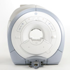
From GE Healthcare;
The GE Signa HDx MRI system is a whole body magnetic resonance scanner designed to support high resolution, high signal to noise ratio, and short scan times.
The 1.5T Signa HDx MR Systems is a modification of the currently marketed GE 1.5T machines, with the main difference being the change to the receive chain architecture that includes a thirty two independent receive channels, and allows for future expansion in 16 channel increments. The overall system has been improved with a simplified user interface
and a single 23" liquid crystal display, improved multi channel surface coil connectivity, and an improved image reconstruction architecture known as the Volume Recon Engine (VRE).
Device Information and Specification CLINICAL APPLICATION Whole body CONFIGURATION Compact short bore Standard: SE, IR, 2D/3D GRE and SPGR, Angiography: 2D/3D TOF, 2D/3D Phase Contrast; 2D/3D FSE, 2D/3D FGRE and FSPGR, SSFP, FLAIR, EPI, optional: 2D/3D Fiesta, FGRET, Spiral, Tensor, 2D 0.7 mm to 20 mm; 3D 0.1 mm to 5 mm 128x512 steps 32 phase encode POWER REQUIREMENTS 480 or 380/415 less than 0.03 L/hr liquid helium | | | | | |
| | | | |
| | | |
|
| |
 | Look
Ups |
| |


